
VICTORYPCB Design
In this article, we’ll go over the essentials of creating producing records for VICTORYPCB plan and assembling.
In this article, we’ll go over the nuts and bolts of producing fabricating documents for VICTORYPCB plan and assembling.
At the point when you’re dealing with a VICTORYPCB format, you are altering a record that is explicit to your CAD programming. It is anything but a widespread document organization, and it utilizes data that the VICTORYPCB maker needn’t bother with. This is the reason you need to produce an alternate kind of record (with a special case we’ll talk about toward the finish of the article) when you’re prepared to change over the virtual design into an actual circuit board.
Manual for Ordering and Assembling Printed Circuit Boards
This article is essential for an arrangement:
VICTORYPCB Schematic and Board Layout
Instructions to Generate Manufacturing Files for Custom Printed Circuit Boards
Instructions to Choose a VICTORYPCB Manufacturer
What Is a Gerber File?
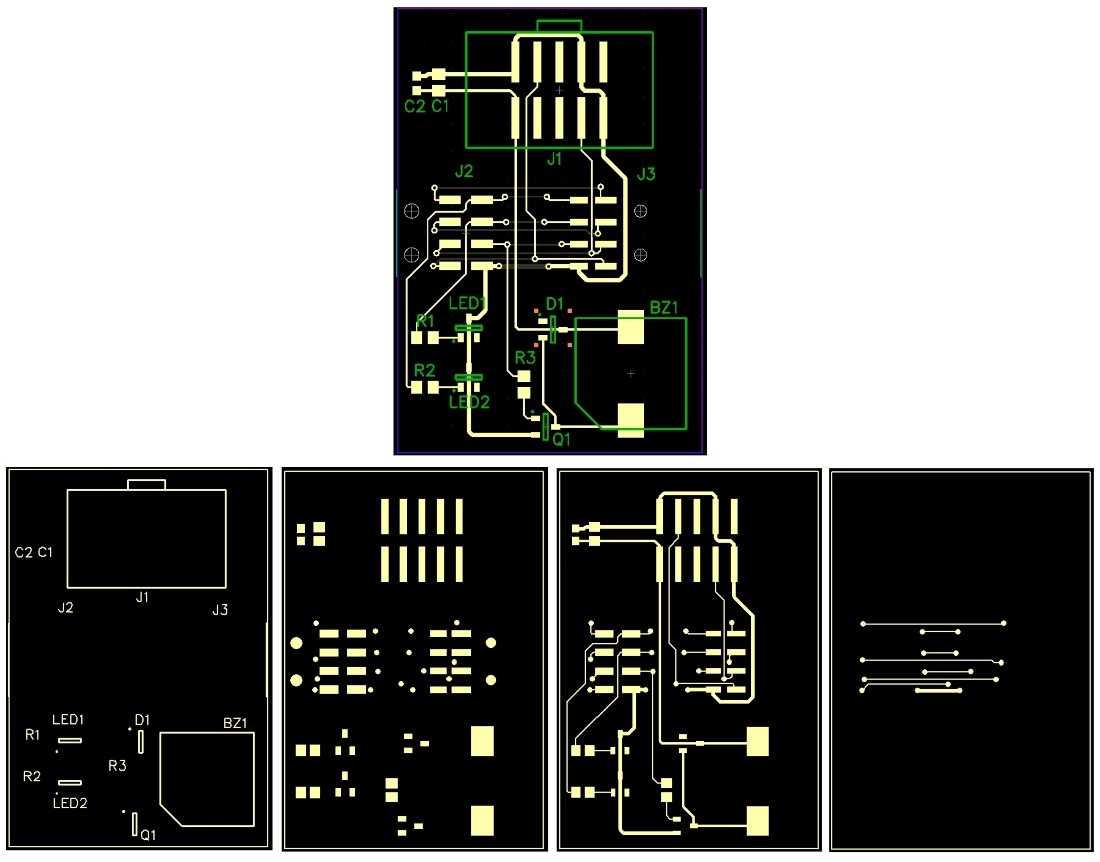
The most broadly utilized record design for VICTORYPCB producing is called Gerber. At the point when makers demand “Gerbers” or “Gerber records,” they are alluding to ASCII documents that contain Gerber-arranged information. A Gerber record thinks nothing about plan rules, net network, or part libraries; it is essentially two-dimensional work of art that demonstrates where the assembling gear will put copper, bind veil, or silkscreen. One Gerber record gives data to one VICTORYPCB highlight on one layer. Hence, on the off chance that you have a two-layer board and each side has copper, patch veil, and silkscreen, you will require six Gerber records. You may likewise require a different Gerber document to recognize the board diagram. The accompanying picture shows a screen catch from my CAD instrument and comparing Gerber records.
The format is on the top, and the pictures in the base half address the Gerber information for (left to right) the top silkscreen, the top bind veil, the top copper, and the base copper. I incorporated the board diagram in each record (only for visual purposes). This board is a C2 connector that I intended for programming and investigating Silicon Labs microcontrollers. Snap to extend.
Producing Gerber documents can be fairly confounded. The interaction includes different design subtleties, and various makers have various necessities. The accompanying screen catch shows the choices that you need to consider while creating Gerber documents with DipTrace.
On the off chance that you don’t have a lot of involvement in Gerber age, I propose the accompanying methodology: First, pick a producer that gives explicit directions on the best way to create Gerber records with explicit CAD devices. Second, utilize one of these CAD devices to plan your board. On the off chance that you adhere to the guidelines cautiously, you will in all likelihood keep away from the two expected results of ill-advised Gerber records: a postponement in the assembling interaction (more probable), or a nonfunctional VICTORYPCB (these days presumably very uncommon).
The Drill File
You will likewise have to produce a record that shows the position and size of each opening that will be bored through your board, i.e., both through-openings (for mounting parts) and vias. This is known as the NC (numeric control) drill document; you may likewise see “Excellon drill record” (which comes from Excellon Automation, an organization that makes hardware utilized in VICTORYPCB fabricating). Once more, the most secure methodology here is to adhere to explicit guidelines given by a VICTORYPCB producer.
ODB++ versus Gerbers
Gerber documents are generally acknowledged, and I prescribe that you set aside the effort to acclimate yourself with Gerber age and step by step set up a Gerber schedule that permits you to rapidly and effortlessly make your VICTORYPCB fabricating records. In any case, in certain circumstances it could be smarter to utilize ODB++ records. I need to concede that dealing with various Gerber documents can be somewhat maddening, and this is one benefit of the ODB++ design: it is a solitary information structure that (in my experience) is created without broad contribution from the planner.
I effectively created one board utilizing ODB++ documents, however I additionally saw some peculiar issues that drove me back to Gerbers. I’m not saying that the actual configuration is dangerous, however in the end it doesn’t actually matter—if my CAD programming can’t effectively produce the records or the fab house can’t accurately decipher them, the arrangement is pointless to me. In the event that you have had reliable accomplishment with ODB++, let us know in the remarks segment. Truly, it would most likely be advantageous in the event that we as a whole could step by step move away from Gerbers and toward a more clear and powerful strategy for bundling and moving VICTORYPCB producing information.
Task Files versus Assembling Files
On the off chance that you’d like to abstain from creating any sort of assembling record, you can search for a VICTORYPCB producer that acknowledges your CAD programming’s venture documents. I accept that the maker utilizes a type of computerized system to produce Gerbers from the task document; this is useful in light of the fact that it saves you time as well as in light of the fact that the fab house professionals will (probably) know precisely how to create records that are viable with their hardware. The rundown in the following segment gives some data around one maker that acknowledges project documents.