
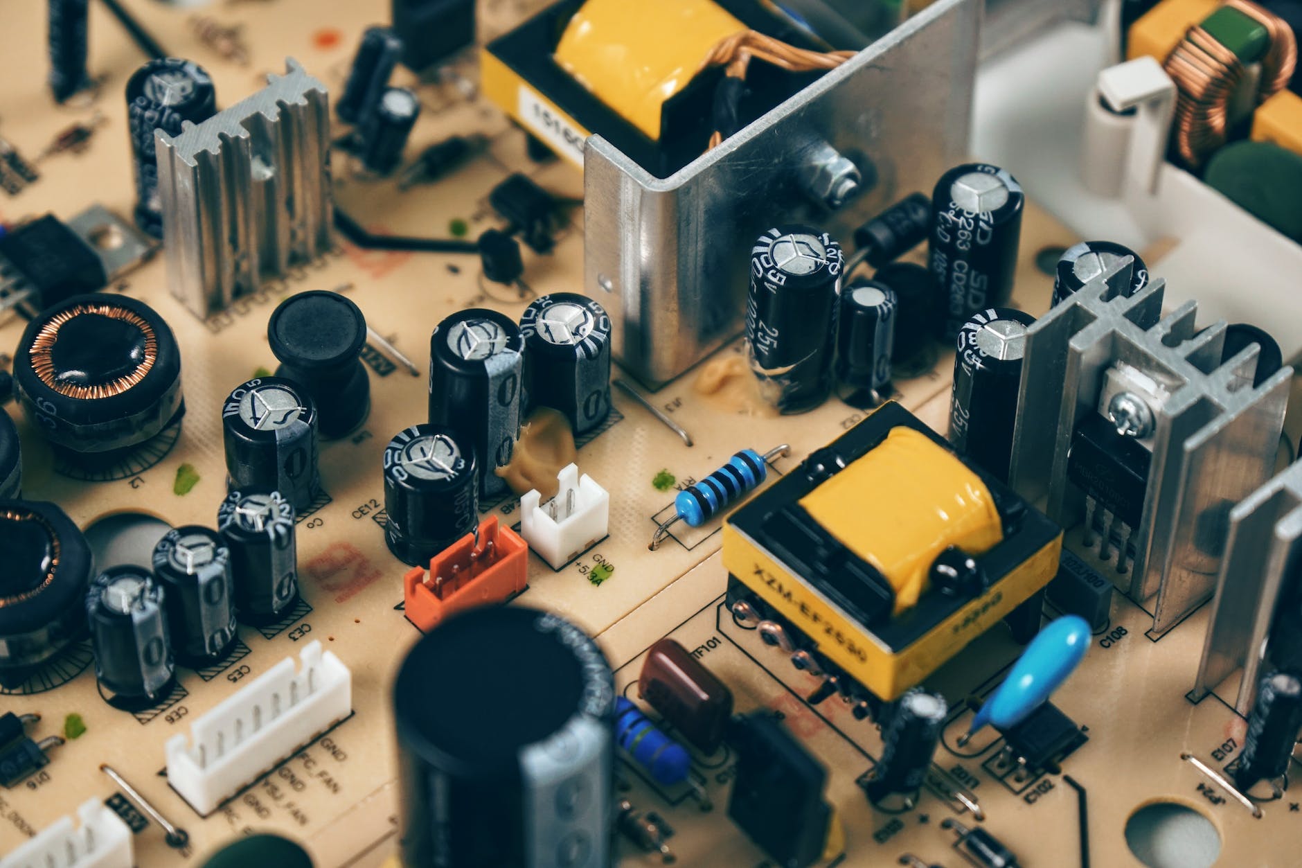
Circuit Boards
Boards with printed circuits are found in nearly every modern electrical gadget. Their critical component is an electronic component mounted on the printed circuit board. The two ways of connecting elements to a board with printed circuits are surface mounting and through installation. In this article, we characterize surface-mounting technology as a fully automated procedure in most cases.
Surface mount technology has advanced rapidly since the 1970s. As a consequence, it has emerged as an important component of the worldwide electronics market. As electronics as well as their constituent parts shrink, surface mounting will ultimately prevail over coated mounting. Furthermore, surface mount technology assures that electronic circuit boards can hold a large number of components without sacrificing performance.
What precisely is surface mounted technology?
STM is a way of placing PCB components. A surface mounted device is generally utilized for affixing electronic components to printed circuit boards and can be installed from either side if necessary. Surface-mount parts are typically compact, with flat enclosures and solder points shaped like flanges extending from the housing ends.
To construct this installation correctly, you have to be very careful when arranging the various electrical elements on the pads. So that surface-mounting technology is carried out on the proper manufacturing lines.
Precision and velocity constitute two of the primary distinguishing features of SMT manufacturing machines. As a result, the possibility of incorporating robotics into high-volume sequential manufacturing is enhanced.
Surface mount advantages and disadvantages
Pros
- Miniaturized components
The component concentration (the number of parts in an identified area) is significantly higher, and each part has many more connections. Manufacturing setup time and costs were reduced. As a result, less drilling is necessary.
- Assembly is made easier and faster by automation.
When components are mistakenly positioned on an iron for soldering, the surface pressure of the liquid solder pulls them into appropriate alignment relative to the solder pads.
- The two faces of the circuit board are used during component positioning.
Reduced interconnection resistance and inductance enhance high-frequency performance and reduce the likelihood of interference.
- Superior structural efficiency in the face of shaking and trembling.
SMT components are frequently less expensive than through-hole counterparts.
Cons
- Prototype construction
Manually assembling a prototype or doing component-level repairs is more difficult.
- Surface-mount devices do not work with breadboards.
Heat cycling has been shown to degrade solder junctions in surface-mount electronics. Surface mount technology is not suitable for significant, consequential, as well as high-voltage parts, such as those utilized in power circuits. Components that are subjected to continual mechanical stress should not employ SMT as their sole connecting approach.
When is surface mount technology appropriate?
SMT is currently widely used in all stages of PCB fabrication and assembly. This is due to the fact that it allows for more gadgets to be crammed into an amount of space. As a result, the components are smaller, and several outperform their predecessors. They also work well with automated technology, requiring no human intervention.
Working with interconnected components meant that automatic positioning was never a definite thing. All wires had to be tailored to fit the exact distance between adjacent holes, although even then, they would not always stay in place. All components in a conventional PCB construction are automatically positioned.
Manual intervention is rarely required. When high-quality circuit boards are used, the need to change a design so that elements fit precisely is greatly minimized. Because of its capacity to improve performance and durability while lowering processing and handling costs, surface mounting technology has become an essential component of PCB design.
By allowing components to be mounted in place, solder-less surface-mount tech (https://workmanship.nasa.gov/lib/insp/2%20books/links/sections/701%20General%20Requirements.html) eliminates the need to punch holes in the printed circuit board. SMT parts are not only smaller, but they are also meant to be more durable. As a result of the improved ability to hold a greater number of parts on each board, PCBs have gotten denser, more efficient, and increasingly compact.
For through-hole attachment, component leads are placed into holes that have been drilled on a bare PCB. Until the 1980s, the through-hole approach was the standard for circuit assembly. THT is widely suspected of being phased out over time in order to embrace Surface Mount, which provides significant savings in expenses and greater efficiency.
Nonetheless, despite its waning appeal, the through-hole technique is useful in the age of SMT, providing many benefits and niche applications. The most obvious advantage of straight-hole tech is its longevity; at the moment, annular bands provide a long-lasting connection.
Circuit Boards
Surface mount technology applications
- Electronics for the home.
- Services for telecommunications
- Medical supplies.
- Regulation methods in the industrial sector.
- Military and aerospace hardware.
What exactly is included in the SMT board building procedure?
During assemblage and manufacturing (PCB), electrical components are put directly onto the PCB’s surface using surface mount technology (SMT). This technology allows for a greater amount of the assembly work required to create a functional board to be done automatically during the manufacturing process.
A variety of factors ought to be considered while selecting an SMT manufacturer
The quality of the materials utilized.
The major consideration in SMT manufacturing is the material used, and the material’s operation has a direct impact on the soldering reflow quality.
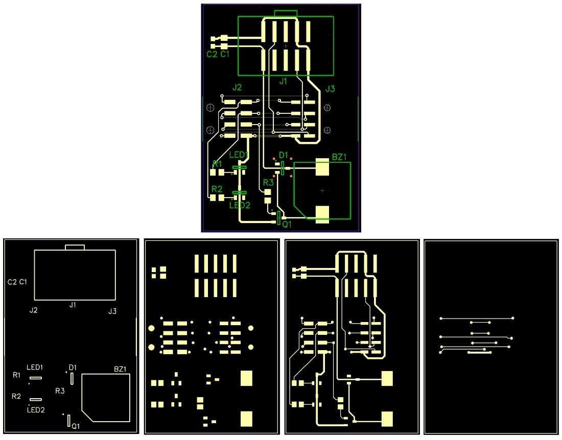
PCB pad configuration
For the SMT process to work well, the PCB design needs to be exact.
Mold design and construction
Solder paste applied to a printed circuit board, also known as a PCB, is a design marvel. The exactitude of the mold’s structure, on the other hand, has a direct impact on the final result of the printed soldering paste.
Prepress circumstances
Blade acceleration, pressure, cleaning methods, and frequency are all important factors in standard printing operations.
Device and equipment utilization
High-density printing using fewer units per board necessitates meticulous, repetitive labor, which has an impact on the solder paste’s stability.
Connections between components
The devil is in the details since correctly using components necessitates careful component selection, precise connection, and pressure application.
Performing solder reflow
Surface mount technologies will advance if the process of reflow soldering can consistently produce good results. To achieve this purpose, the board’s connections must be of the highest standard.